This topic is ONLY relevant to security gateways. It is NOT relevant to managed switches.
Overview
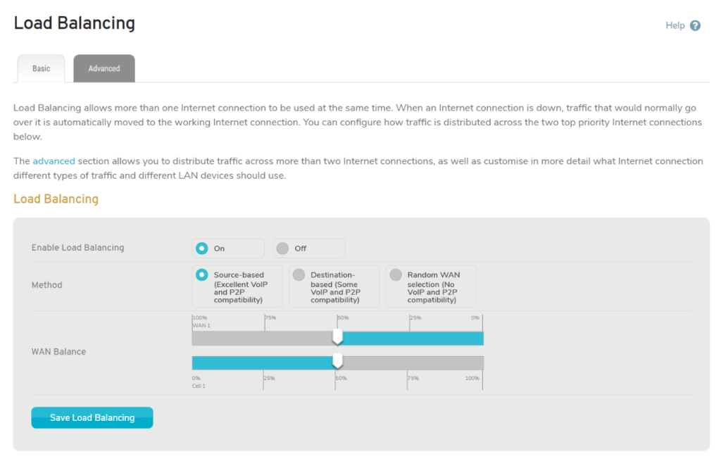
Figure 1. Example Load Balancing Page
The Load Balancing page (Fig. 1) is where you can enable and configure load balancing for the selected Mako device.
Load Balancing allows more than one Internet connection to be available at the same time. When an Internet connection is down, traffic that would normally use that connection is automatically rerouted to a working connection.
You can configure how traffic is distributed across the two top priority Internet connections using the Basic Settings tab.
The Advanced Settings tab allows you to distribute traffic across more than two Internet connections, as well as to customize in more detail which Internet connection different types of traffic and different LAN devices should use.
Basic Settings
Enable Load Balancing
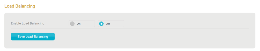
Figure 2. Example Basic Settings Form with Load Balancing Disabled
Load balancing is disabled by default (Fig. 2) and must be enabled before any other load balancing settings will be available. To enable, set the Enable Load Balancing radio button to “On” and then click the “Save Load Balancing” button.
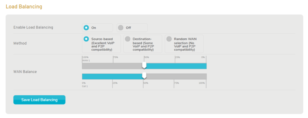
Figure 3. Example Basic Settings Form with Load Balancing Enabled
After enabling load balancing, the other load balancing settings will be visible (Fig. 3).
Method
Choose a method of grouping traffic for distribution. These methods vary based on their compatibility with Voice over IP (VoIP) and peer-to-peer (P2P) networks.
- Source-based (Excellent VoiP and P2P compatibility)
- Destination-based (Some VoiP and P2P compatibility)
- Random WAN selection (No VoiP and P2P compatibility)
You can also use the Advanced Settings tab to create more sophisticated routing rules that supersede this default rule.
WAN Balance
Use the slider to set the percentage of traffic to be distributed to each of the two top priority Internet connections. The default balance is 50% to each connection. Moving the slider left increases traffic to the first connection and decreases traffic to the second connection. Moving the slider right does the opposite.
You can also use the Advanced Settings tab to create more sophisticated routing rules that supersede this default rule.
Save Button
To save any Basic Settings tab changes, click the “Save Load Balancing” button.
Advanced Settings
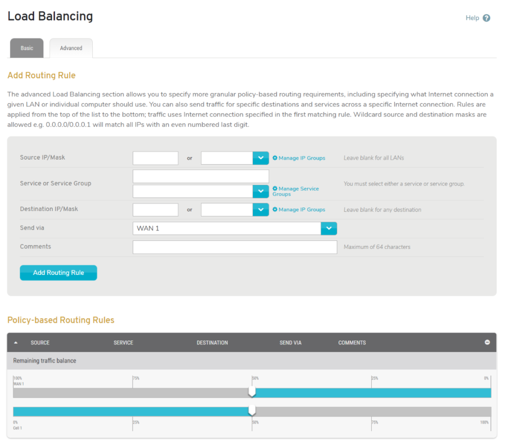
Figure 4. Example Advanced Settings Tab
The Advanced Settings tab (Fig. 4) allows you to create policy-based routing (PBR) rules, which provide more granular control than the basic settings offer. Creating PBR rules is also necessary if you want to use more than two Internet connections.
PBR rules are applied from the top of the PBR rules list to the bottom, i.e. traffic uses the Internet connection specified in the first matching rule. You will need to sort the list to ensure that the rules are enforced in the desired order.
Add Routing Rule
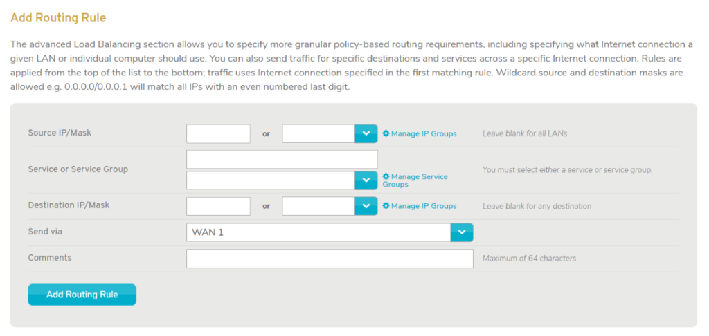
Figure 5. Example Add Routing Rule Form
Use the Add Routing Rule form (Fig. 5) to create a PBR rule.
Source IP/Mask
If you want this PBR rule to filter traffic by its source, enter either an IP or mask value that matches the desired traffic in the text field. Wildcard masks are allowed, e.g. “0.0.0.0/0.0.0.1” will match all IPs with an even-numbered last digit.
To use a predetermined group of IP addresses, choose an IP Group from the dropdown field and leave the text field blank. To create an IP Group, click the “Manage IP Groups” link to visit the appropriate CMS page. This link takes you away from the current page, so you will lose any unsaved values in this form.
Leave both fields blank to allow traffic from all sources.
Service or Service Group
If you want this PBR rule to filter traffic by service, use the service type selector or the service group dropdown to specify the service type values that match the desired traffic.
Leave both fields blank to allow traffic for all services.
Service Type Selector
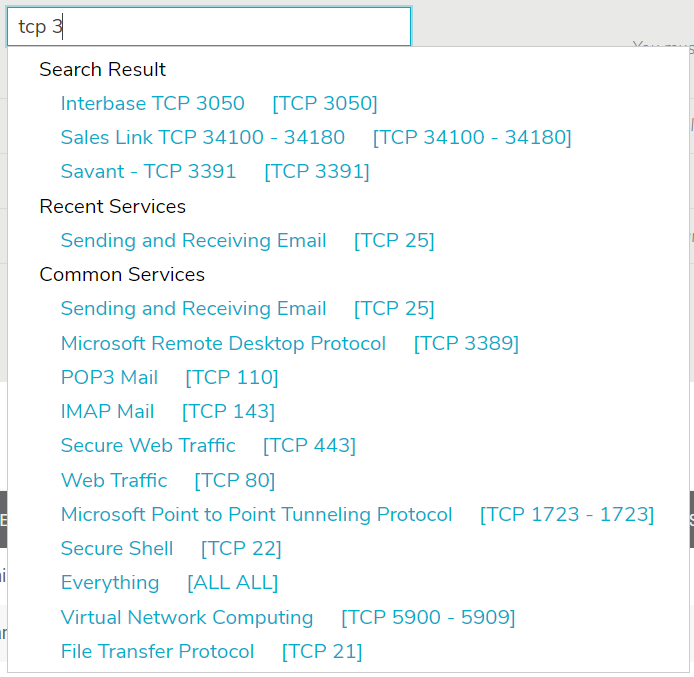
Figure 6. Example Service Type Selector
Use the service type selector (Fig. 6) to specify the service type of the traffic to which the new rule will apply. The service type selector will display a Search Results list as you type. Below the Search Results list, you will see lists of Recent Services (if any have been selected recently) and Common Services. If the desired service type is visible in one of these lists, click the service type to select it.
Service Group
To use a predetermined group of services, choose a Service Group from the dropdown field and leave the service type selector blank. To create a Service Group, click the “Manage Service Groups” link to visit the appropriate CMS page. This link takes you away from the current page, so you will lose any unsaved values in this form.
Destination IP/Mask
If you want this PBR rule to filter traffic by its destination, enter either an IP or mask value that matches the desired traffic in the text field. Wildcard masks are allowed, e.g. “0.0.0.0/0.0.0.1” will match all IPs with an even-numbered last digit.
To use a predetermined group of IP addresses, choose an IP Group from the dropdown field and leave the text field blank. To create an IP Group, click the “Manage IP Groups” link to visit the appropriate CMS page. This link takes you away from the current page, so you will lose any unsaved values in this form.
Leave both fields blank to allow traffic to all destinations.
Send Via
Choose the Internet connection that will handle traffic that matches this PBR rule.
Comments
Enter a brief but informative description of what this PBR rule does. The maximum length is 64 characters.
Add Button
Click the “Add Routing Rule” button to create the PBR rule. It will then display in the PBR rules list below.
Since new PBR rules appear at the bottom of the list, whenever possible you should create your PBR rules in the same order that you want them to display. This can reduce time spent sorting the list.
Policy-based Routing Rules
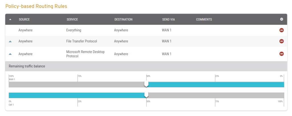
Figure 7. Example Policy-based Routing Rules List
The Policy-based Routing Rules list (Fig. 7) displays PBR rules created using the Add Routing Rule form (Fig. 5) and allows you to sort the list to ensure that the rules are enforced in the desired order. At the bottom of the list is a slider that illustrates the default rule used by any traffic that does not match the other rules in the list.
Rule Columns
- Move – move up arrow icon buttons
- Source
- Service
- Destination
- Send Via
- Comments
- Delete – delete minus icon buttons
Rule Actions
Delete Rule
Click the minus icon button to delete the rule.
Raise Rule Priority
Click the up arrow icon button to raise the rule one position on the list.
Remaining Traffic Balance
The Remaining Traffic Balance slider illustrates the default rule used by any traffic that does not match the other rules in the list. This default rule is configured using the Basic Settings tab.